Go to the content
PROFECTRONICS
Focus area · Fluid engineering · Electrical

Data centre cooling and chip emulator

On an accelerator module, 2 temperature limits apply next to each other: 105 °C for the logic and 85 °C for the memory stack. Profectronics builds test benches that emulate the heat source zone by zone, condition the cooling circuit and measure the temperature gradient.

Emulator

Emulation of the heat source

The emulator replaces the chip with a heated surface of known power and known area. It applies the same heat flux density to the same area.

The heater plates come from a specialised supplier. Profectronics builds the test bench around the heater plates.

The characteristic values of the heated surfaces come from the data sheet of the supplier. Before each design, the supplier confirms the characteristic values again. Profectronics supplies the system around the emulator and is responsible for it: control, measuring chain, safety and test record.

QuantityRange (design)Remark
Power densityup to 200 W/cm²Design target. The logic chip of a published multi-chip module reaches 295.86 W/cm².
Electrical powerup to 5.1 kW per zoneTypical operating point 3 500 W at 240 V, a separate power supply for each zone
Zones per emulator1 to 4Each zone has a separate control channel and a separate power supply
Load stepSequence up to approximately 2 HzRise time 50 ms and fall time 100 ms under load, limited by the response time of the power supply
Flow temperature+15 to +60 °CWarm water cooling included
Flow rate0.5 to 120 L/minPer test specimen, supply from the test field above this value
Operating pressure0.5 to 6 barTypical secondary circuit in the rack
MediaWater-glycol, deionised water (DI water), dielectric fluidsConductivity monitored
Heat balanceFluid side ± 3.7 %, electrical ± 0.2 to 0.5 %At a temperature difference of 10 K, error chain in the section on measurement uncertainty
Heat exchanger Secondary side Mains water Primary side Test medium CONDITIONING CIRCUIT · MAINS WATER Mains water Filter Pump Heater Cooling valve Drain heats cools Test branch 2 to 4 Space and connection kept free PROCESS CIRCUIT · TEST MEDIUM Tank Process pump demand-controlled Manifold Collector Test specimen Cold plate FI PI TI PI Δp and heat balance across the test specimen Overflow valve holds the manifold pressure Return to the tank Two-phase module Condenser · receiver · vapour quality Flow, conditioned Return prepared, not in the basic configuration FI flow · PI pressure · TI temperature
Fig. 1 · Conditioning circuit and process circuit with the heat exchanger between them. Dashed: prepared, not in the basic configuration.
Multi-zone emulation

Power density and temperature limits per zone

Different temperature limits apply in the same package. The power loss is not uniform across the area.

POWER DENSITY IN THE SAME PACKAGE 295.86 W/cm² Logic chip 52.08 W/cm² Memory stack Factor 5.7 PERMISSIBLE JUNCTION TEMPERATURE 105 °C Logic chip 85 °C Memory stack 20 K difference on one heat sink Sources: OCP paper “30 °C Coolant — A Durable Roadmap for the Future” · International Journal of Heat and Mass Transfer
Fig. 2 · 2 limit values on one component, with a difference in power density by the factor 5.7.

A test body with uniform heat does not show this difference. It gives a mean thermal resistance across the full area. This mean value does not show if the memory stack stays below 85 °C while the logic area reaches 105 °C. For this reason, the emulator has zones with separate control: each zone has a control channel, a power supply and a power measurement.

A copper spreader in the cooling concept makes the heat map across the area more uniform. The difference between the logic area and the memory area stays, because different limit values apply and the heat flow is not uniform. The spreader changes the necessary resolution. One measuring point is not sufficient, also with a spreader. Profectronics designs the emulator for a maximum of 4 zones.

  • Number of zones The power supplies are stackable. The heat removal of the fluid circuit sets the limit. 4 zones at full power need more heat removal than 4 zones that share the power of one test specimen.
  • Zone geometry The interface to the test specimen sets the number, position and size of the zones. An emulator with an incorrect division is not usable for the test specimen.
  • Memory power HBM4E (High Bandwidth Memory) up to 80 W per device, HBM5 approximately 100 W per stack from 2028. 8 stacks give 800 W next to approximately 2 kW of logic power. The memory has the lower temperature limit and the larger part of the area.

Sources: temperature limits from the paper “30 °C Coolant — A Durable Roadmap for the Future” of the Open Compute Project (OCP). Power densities from a study of jet impingement cooling in the International Journal of Heat and Mass Transfer. Data on future component generations come from trade press and market reports, not from manufacturers. They show the trend and are not a specification.

Measurement uncertainty

Measurement uncertainty of the thermal resistance

The thermal resistance is the quotient of temperature difference and heat flow. Both quantities come from a measurement and have an uncertainty.

On the fluid side, the heat flow is the product of density, flow rate, heat capacity and temperature difference. At a difference of 10 K, the flow rate contributes ± 1.5 % and the density from the temperature contributes ± 0.2 %. The temperature difference contributes ± 3.4 %, with 2 independent class A sensors.

√(1.5² + 3.4² + 0.2²) % = ± 3.7 %

Approximately four fifths of this value come from the temperature measurement, not from the flow measurement. The temperature part increases in inverse proportion to the temperature difference. As a result, the total uncertainty is ± 7.0 % at 5 K and ± 2.3 % at 20 K. A small temperature difference that the test specimen requires increases the uncertainty. 2 measures decrease it:

  • Matched sensor pair Tolerance 1/10 class B (trade name, not a class from a standard). The temperature part decreases from 3.4 % to 0.7 %, the total uncertainty to approximately ± 1.7 % at 10 K. This measure has a larger effect than a more accurate flow meter.
  • Electrical measurement Measure the heat source electrically: ± 0.2 to 0.5 % with a power measurement, independent of the power supply. For this reason, Profectronics always includes a separate power measurement on the emulator.

A statement such as “U(Rth) ≤ 2 %” is not verifiable without data on the temperature measurement and the temperature difference. With 2 separate sensors and a difference of 10 K, this value is not possible. For this reason, Profectronics gives the error chain and the measuring instruments that support the value.

Electrical side

Selection of the power supply from the performance map

Conventional programmable power supplies have a rectangular performance map. The current limit at 100 V is the same as at 300 V.

The adjustable power limit of these units is only an additional limit. At low voltage, it does not permit a higher current. Autoranging units with a power map supply their rated power across a wide voltage range. The calculation that follows applies to the conventional class of units.

1 000 W 2 000 W 3 000 W 4 000 W 5 000 W 240 available at 240 V: 17 A = 4 080 W 5 000 W need 20.8 A at this point, outside the performance map 0 100 200 300 0 5 10 15 17 20 Output voltage in V Output current in A Performance map of the unit: 0…300 V · 0…17 A Lines of constant power
Fig. 3 · Lines of constant power over the performance map. At the operating point, the product of voltage and rated current is available, not the rated power on the nameplate.

A unit with 300 V and 17 A has 5.1 kW on the nameplate and supplies 4 080 W at 240 V. As a result, up to 4 000 W per zone are possible. At 240 V, 5 000 W need a current of 20.8 A. 5 000 W are only possible above 295 V.

The next smaller size with 11.5 A and 3.45 kW supplies 2 760 W at 240 V and does not reach 3 000 W. Between the two sizes, there is no unit with a height of 1 rack unit. For this reason, a selection by rated power gives a power supply that is too small. The error becomes visible at commissioning, when the zone does not reach its setpoint.

The readback of the power supply shows the manipulated variable and is not a measurement. For the heat balance, Profectronics measures the supplied power a second time with a separate shunt and an isolated transducer. Above 120 V DC, the voltage is not a safety extra-low voltage (SELV). For this reason, DC isolation, protection against direct contact and the connection to the safety circuit are part of the emulator.
Layout

Layout with media rack and electrical rack

The test bench has 2 separate fluid circuits and 2 separate racks. As a result, the media side and the electrical side are independent for maintenance and extension.

The conditioning circuit moves mains water through a filter and a circulation pump. An electric heater adds heat. A control valve releases warm water into the drain and thus removes heat.

The process circuit moves the test medium from the tank through the manifold, the test specimen and the collector back to the tank. Test media are water-glycol, DI water or a dielectric fluid. The heat exchanger is the only connection between the two circuits. Mains water and test medium have no contact. As a result, the test medium stays clean and in a known condition.

The control loop holds the temperature at the transfer point, not the temperature at the test specimen. In one half of the control range, the cooling valve opens. In the other half, the heating element heats. A dead band between the two halves prevents simultaneous operation of the valve and the heating element. A feedforward control from the specified emulator power compensates the load step in advance.

The process pump operates on demand through a frequency converter. It follows the demand of the connected branches, plus a control reserve for the overflow valve. The overflow valve holds the manifold pressure. The operation on demand saves energy and keeps the heat input of the pump low. This heat input goes directly into the heat balance.

RACK 1 Media rack Connection level Mains water · drain · vent Heat exchanger · heater · valves Process pump speed-controlled Tank Manifold and collector free Space for test branch 2 to 4 free Space for a two-phase module RACK 2 Electrical and emulator rack Incoming supply and fuses Control and measuring cards Emulator power supply 1 rack unit per zone free Space for 3 more power supplies Distribution and terminal level free Reserve Operator panel 21 inch Operation · curves · test record arm with height and swivel adjustment on the rack, not in the rack front used in the basic configuration kept free for extension
Fig. 4 · Division into 2 racks of 19 inch. The free space is rack units, not piped connections.
Option

Two-phase module as an extension

Evaporation removes heat at an almost constant surface temperature. This test needs a separate system section. The basic configuration keeps space, a connection point and control channels free for it.

Reason for the design as an option

A large part of the fluids for two-phase immersion cooling belongs to the group of per- and polyfluoroalkyl substances (PFAS). For this group, a European restriction procedure is in progress. The test bench does not make the selection of the fluid in advance. You buy the two-phase module when the fluid is known.

The technical article Two-phase cooling for electronics describes the withdrawal of manufacturers and the status of the procedure.

Measuring chain

Requirements for the measuring chain

The measuring chain sets how reliable the evaluation of a cold plate is.

Test specimens

Test specimens from the component to the distribution unit

The test bench does tests on single components and on complete distribution units.

Test specimenTest and measurement
Cold plate and manifoldEmulation of the heat source with a defined power density. Measurement of thermal resistance, pressure loss and temperature distribution, with the effect of the contact pressure.
ManifoldUniform distribution across many outlets, pressure loss as a function of the flow rate, cavitation limit. The measurement also records deviations at the outer outlets.
Quick-disconnect coupling (Universal Quick Disconnect, UQD)Connection cycles up to the manufacturer data, usually up to 5 000. Measurement of residual leakage and flow across the full cycle.
Coolant distribution unit (CDU)Final test of the complete unit: capacity at different flow temperatures, control deviation, leak tightness, behaviour at a pump change in operation (hot swap).
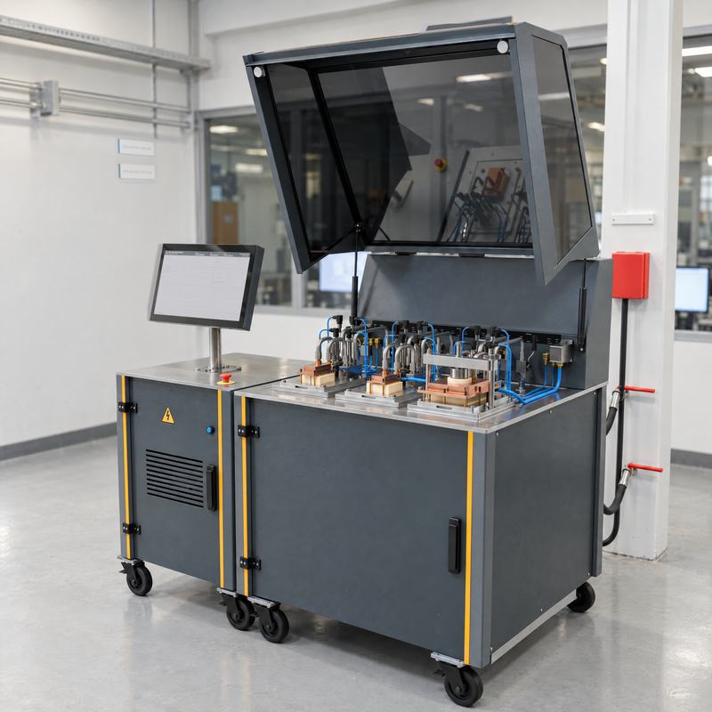
Visualisation · Mobile test station with protective hood

Mobile test station

Construction: Profectronics also builds mobile test stations on castors, with a protective hood and a control desk. The figure shows this construction with test fixtures for cold plates.

Design

Design range

The table gives the limits of the modular system.

FeatureValue (design)Remark
Test specimensCold plate, manifold, quick-disconnect coupling, CDUComponent to complete unit
Power densityup to 200 W/cm²Chip emulator
Load stepEdge in the range of tenths of a secondTest of the control deviation
Flow temperature+15 to +60 °CWarm water cooling included
Flow rate0.5 to 120 L/minPer test specimen
Operating pressure0.5 to 6 barSecondary circuit
MediaWater-glycol, DI water, dielectric fluidsConductivity monitored
Leak tightnessPressure decay, heliumBefore commissioning and in series production
TraceabilityTest record per test specimenTime stamp, equipment number, calibration status

The values are design limits and not a commitment for a specific project. Profectronics built an emulation of a chip cooling with 2 500 W. Profectronics designed a complete direct-to-chip test bench with load step. The functional specification defines the values for your system.

Other focus areas

Other focus areas and enquiry

For the design, 5 items of data are sufficient: test specimen, medium, ranges for pressure, flow rate and temperature, installation site and date. A customer specification helps, but it is not a condition.