Test benches for power electronics
A converter does not usually fail at a steady-state operating point. It fails after many load changes. Profectronics builds test benches that measure the heat path from the liquid-cooled module into the coolant, for each load point and over the service life.
Heat path and service life
The test bench measures the path of the heat from the module into the coolant and the change of this path over time.
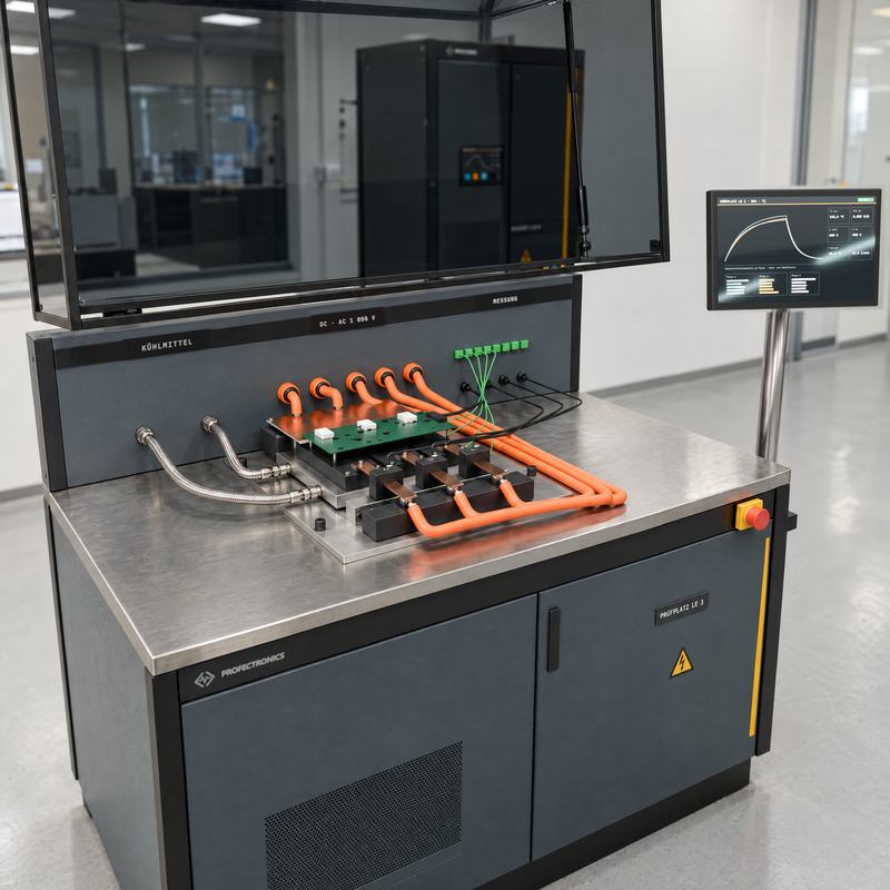
- Thermal resistance Rth From the junction into the coolant, for each load point.
- Power cycling Load changes up to the failure criterion, for the evaluation of the service life.
- Contact pressure Effect of the contact pressure between the module and the heat sink, measured.
- Load Regenerative DC load and AC load, load current instead of a heater resistor.
- Deionised water circuit Cooling circuit with deionised water (DI water), conductivity monitored.
- Acquisition Galvanically isolated, up to the kHz range.
Electrical and thermal characteristic values
The test bench supplies current to the test specimen and measures the heat path at the same time.
| Quantity | Value (design) | Remark |
|---|---|---|
| Load | DC and AC, regenerative | Instead of a heater resistor |
| Test current | up to 1 000 A | Depends on the module |
| Voltage | up to 1 500 V DC | Depends on the application |
| Measured quantity | Rth per load point | Junction to coolant |
| Acquisition | up to 50 kHz | Galvanically isolated |
| Coolant | DI water, water-glycol | Conductivity < 2 µS/cm, monitored |
| Flow temperature | +15 to +65 °C | Warm water cooling included |
| Flow rate | 1 to 60 L/min | Per test specimen |
The values are limits of the modular system and not a commitment for a specific project. The functional specification defines the values for your system.
Load cycles up to the failure criterion
The power cycler applies current to the module in cycles until a failure criterion applies. It measures the junction temperature without a sensor, through the collector-emitter voltage VCE at a low measuring current. VCE is the temperature-sensitive electrical parameter (TSEP). The sequence follows the guideline AQG 324 of the European Center for Power Electronics (ECPE).
- Power cycling with cycles of seconds (PCsec) Short current pulses with steep temperature swings. The test applies stress to the bond wires and the chip solder. It tests the packaging technology near the chip.
- Power cycling with cycles of minutes (PCmin) Slow temperature increase through the full module. The test applies stress to the solder layer to the base plate. It tests the large-area heat path.
- Cooling curve Thermal impedance from the step response, resolved layer by layer from the chip into the coolant. The change over the cycles shows the layer that ages.
- Switching behaviour in double pulse (DP) Switching energies and overvoltages per operating point, on the same test specimen and the same cooling circuit.
Tests and their standards
Standards and guidelines specify the qualification of power modules. Profectronics designs the test benches for these procedures. The test record contains the proof.
| Test | Basis | Stress and measured quantity |
|---|---|---|
| Power cycling, cycles of seconds (PCsec) | ECPE AQG 324 QL-01, IEC 60749-34 | Short current pulse with steep temperature swing. Applies stress to bond wires and chip solder. Failure criterion typically +5 % VCE or +20 % Rth. |
| Power cycling, cycles of minutes (PCmin) | ECPE AQG 324 QL-02, IEC 60749-34 | Slow temperature increase through the full module. Applies stress to the solder layer to the base plate. Same criteria, different damage mechanism. |
| Thermal resistance junction to case Rth(j-c) | JEDEC JESD51-14 | Transient dual interface: 2 cooling curves, with and without thermal interface material. The separation point of the structure function gives the transition junction → case. |
| Thermal impedance Zth | JEDEC JESD51-1 (electrical test method for the junction temperature), IEC 60747-9 | Step response over time. The structure function resolves it layer by layer. The change over the cycles shows the layer that ages. |
| Switching behaviour, double pulse | IEC 60747-9 | Turn-on energy Eon, turn-off energy Eoff and switching times per operating point. Integration limits from the thresholds of the standard (10 %, 90 %, 2 %). |
| Temperature cycles (Thermal Shock Test, TST) | IEC 60068-2-14, AQG 324 | Passive cycles without load current. Separates the thermomechanical fatigue from the effect of the internal power loss. |
| Continuous junction stress (High Temperature Reverse Bias, HTRB, and High Temperature Gate Bias, HTGB) | IEC 60749-23, AQG 324 | Blocking voltage or gate voltage at maximum temperature for a long time. The criterion is the trend of the leakage current. |
| Humidity under voltage (High Humidity High Temperature Reverse Bias, H3TRB) | IEC 60749-5, AQG 324 | 85 °C and 85 % relative humidity under blocking voltage. Tests the passivation and the encapsulation. |
| Safety of the set-up | IEC 62477-1 | Clearances and creepage distances, protective separation, protection against direct contact. The standard applies to the test set-up and to the test specimen. |
Test bench without certification
Profectronics builds the test benches and does not certify. Profectronics designs the systems for the sequences above. The party that does the test is responsible for the execution and the evaluation of the test. The functional specification defines the applicable edition of the standard.
Test specimens from the module to the power stage
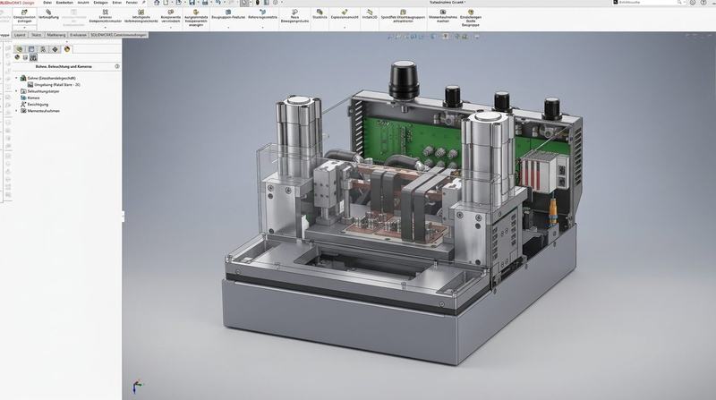
The test bench does tests on single modules and on complete power stages.
- Power modules Modules with insulated-gate bipolar transistors (IGBT) and modules of silicon carbide (SiC): thermal resistance and power cycling.
- Converters and inverters Efficiency, temperature increase and load changes with load current.
- Charger electronics and DC/DC electronics Thermal behaviour and endurance test with liquid cooling.
- Liquid-cooled heat sinks Pressure loss, contact pressure and temperature distribution.
Design range
The table gives the limits of the modular system.
| Quantity | Value (design) | Remark |
|---|---|---|
| Test specimens | Modules, converters, charger electronics | Component to power stage |
| Load | DC and AC regenerative, up to 1 000 A | Up to 1 500 V DC |
| Measured quantity | Rth, efficiency, temperature | Per load point |
| Cooling circuit | DI water, water-glycol | Conductivity monitored |
| Traceability | Test record per test specimen | Time stamp, equipment number |
The values are limits of the modular system and not a commitment for a specific project. The functional specification defines the values for your system.
Other focus areas and enquiry
For the design, 5 items of data are sufficient: test specimen, medium, ranges for pressure, flow rate and temperature, installation site and date. A customer specification helps, but it is not a condition.
