Piping in the frame
Stainless steel pipes, plate heat exchanger and pump are in the frame of the conditioning unit.
Mobile test station
Test station on castors with protective hood and control desk. Figure: Applications and system examples.
Conditioning units supply temperature, pressure, flow rate and humidity as boundary conditions of a test. Profectronics designs them for test tasks from the component to the test field for large engines.
Profectronics builds conditioning units with the fluid system in a frame. Profectronics also builds mobile test stations on castors.
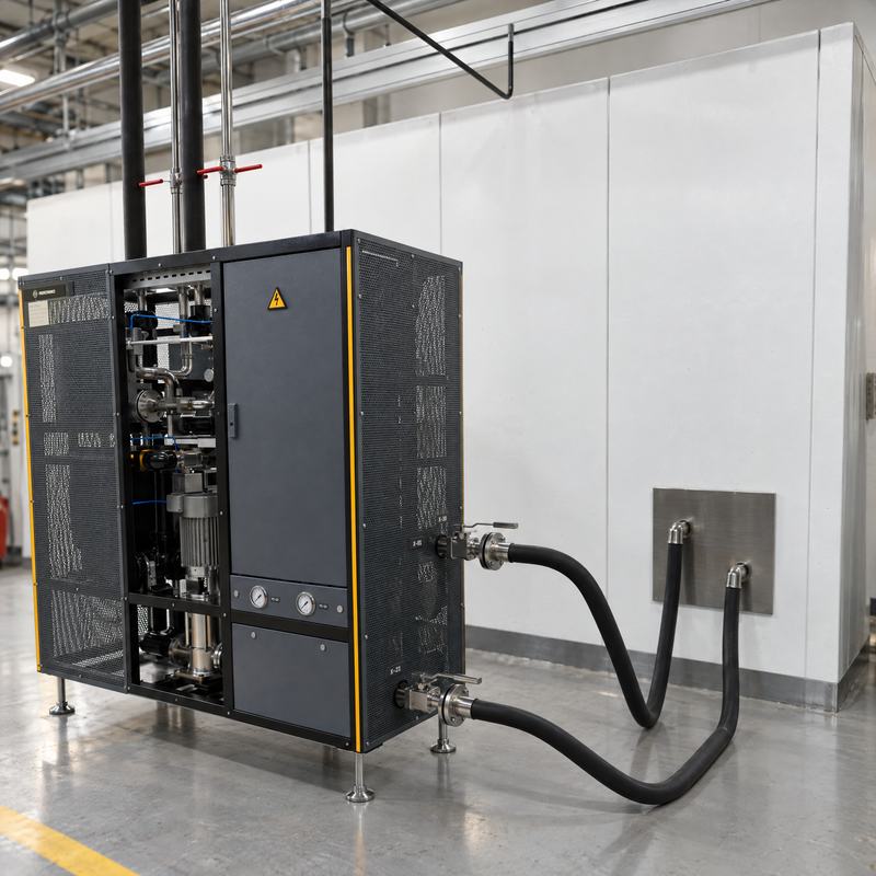
Stainless steel pipes, plate heat exchanger and pump are in the frame of the conditioning unit.
Test station on castors with protective hood and control desk. Figure: Applications and system examples.
The system connects medium, conditioning, control and test process.
Water, glycol, oil, dielectric fluids, fuel, air and gas. Liquid, gaseous or two-phase.
Temperature, pressure, flow rate and, for gases, humidity. Up to 2.5 MW per circuit.
Feedforward and observer, adaptive and predictive. Steady-state control deviation down to ± 0.1 K.
Operation, messages and release. Test record per test run in development and series production.
Temperature, pressure, flow rate and thermal power follow the test task.
| Quantity | Range (design) | Remark |
|---|---|---|
| Medium temperature, liquid media | −30 to +120 °C | Per application, see Fig. 1 |
| Medium temperature, air and gases | −30 to +300 °C | Per application, see Fig. 1 |
| Flow rate | 3 L/h to 180 m³/h | Liquid media |
| Flow rate | up to 8 000 m³/h | Air |
| Thermal power | up to 2.5 MW | Per circuit |
| Steady-state control deviation | down to ± 0.1 K | At a load step up to ± 0.5 K |
| Temperature gradient | 0.1 to 4 K/s | To the test task |
| Humidity | 10 to 90 % relative humidity | Steam humidifier, adsorption dryer |
| Conformity | CE | Machinery Regulation (EU) 2023/1230 for systems that are placed on the market or put into service from 2027-01-20. Pressure Equipment Directive, Low Voltage Directive and EMC Directive, ATEX on request. |
Each medium has its own requirements for materials, monitoring and safety.
| Medium | Application and requirement | |
|---|---|---|
| Water, deionised | Cooling circuits and chip cooling. Conductivity monitored. | |
| Water-glycol | Vehicle circuits and engine circuits. Concentration and quality monitored. | |
| Oils | Lube oil and thermal oil. Vacuum degassing. | 0.5 to 600 mPa·s |
| Dielectric fluids | Direct cooling and immersion. Design for material compatibility. | |
| Fuels, e-fuels | Low pressure and high pressure. Materials FKM, FFKM, PTFE and stainless steel. | |
| Air | Charge air and supply air. Humidity with active control. | |
| Hydrogen | Measurement and conditioning. Leak tightness, purge concept and enabling chain. | |
| Refrigerants | Two-phase, as a module. Design from substance data. |
The diagram shows thermal power and medium temperature per application.
Conditioning units supply coolant, oil and charge air as boundary conditions for the test specimen.
| System | Application | Characteristic values |
|---|---|---|
| Conditioning units | Coolant, oil and charge air as boundary conditions of the test. | up to 180 m³/h Steady-state control deviation ± 0.1 K |
| Calorimeters | Condensers, gas coolers, coolers, charge air coolers and oil coolers. | 8 000 m³/h air Steady-state control deviation ± 0.1 K |
Figures of the two systems: Applications and system examples.
For the refrigerants R744 and R290, pressure and explosion protection are part of the design. The characteristic values and the safety concept are on the page Heat pumps and refrigeration.
Each property of the controlled system needs a separate method. Examples are the dead time from the transport time in the pipes and parameters that change with temperature. A further example is a state in the test specimen that is not measurable.
| Method | Property of the controlled system | Effect |
|---|---|---|
| Model-based feedforward | Known load setting | The feedforward calculates the operating point. It does not build it up through the control deviation. |
| Disturbance feedforward | Measurable load change | The disturbance acts on the actuator before it reaches the controlled variable. |
| Smith predictor | Dead time from the transport time in the pipes | The predictor removes the dead time from the closed loop. |
| Gain scheduling | Viscosity as a function of temperature | The controller parameters follow the operating point and not a compromise. |
| Adaptive control | Different media and masses of test specimens | The control system identifies the parameters of the controlled system in operation and adapts them. |
| Predictive control | Limits of the manipulated variable, load cycles | Setpoint sequence with limits for power and actuator travel. |
| Kalman-Bucy filter | Measured values with noise | State estimate at small temperature differences. |
| Sliding-mode observer | Model uncertainty | Robust estimate of states in the test specimen that are not measurable. |
Operating mode, setpoints, model parameters, messages and enabling chain are on one screen. Each message has an identifier, and each test run has a test record.
For the design, 5 items of data are sufficient: test specimen, medium, ranges for pressure, flow rate and temperature, installation site and date. A customer specification helps, but it is not a condition.
