Go to the content
PROFECTRONICS
Focus area · Fluid engineering

Test benches for heat pumps and refrigeration

A test bench for heat pumps measures a performance map. The map shows the heating capacity and the coefficient of performance as a function of the source and sink temperature. The test bench also does defrost cycles, part-load tests and endurance tests. Profectronics builds the system that conditions the source and the sink, operates the test specimen and records the result with traceability.

Task

Test tasks in the performance map

The test point A2/W35 to EN 14511 does not show the behaviour at a source temperature of −7 °C and a flow temperature of 55 °C. It also does not show the effect of a defrost cycle every 12 min on the operation. For this reason, the test bench covers the full operating range of the unit.

HEATING CAPACITY IN kW 0 4 8 12 16 W35 W45 W55 A−7 / W35 A2 / W35 A7 / W35 A−15 / W55 COEFFICIENT OF PERFORMANCE COP 0 2 4 6 W35 W45 W55 −20 −15 −7 0 2 7 12 20 SOURCE TEMPERATURE IN °C FAMILY OF CURVES Flow temperature 35 °C Flow temperature 45 °C Flow temperature 55 °C OPERATING POINTS POINT kW COP A−7 / W35 8.4 2.8 A2 / W35 10.2 3.7 A7 / W35 11.6 4.4 A−15 / W55 5.7 1.5 TEST CONDITIONS Sink ΔT 5.0 K Source humidity 87 % RH Steady state ± 0.5 K Defrost included Example values for the diagram, not measured values.
Fig. 1 · Heating capacity and COP as a function of the source temperature, for the flow temperatures 35, 45 and 55 °C, with operating points to EN 14511. Example values for the diagram, not measured values.
Conditioning

Conditioning of source and sink

The test bench replaces the environment of the unit. It keeps the source at the specified temperature. It removes the heat from the sink with a control loop.

CircuitMediumRange (design)
Source brine/waterWater-glycol, water−15 to +40 °C
Source airClimatic chamber, temperature and humidity controlled−25 to +55 °C
Sink heatingHeating waterup to 80 °C
Flow rate per circuitcontrolled0 to 30 L/min
Control deviationsteady state± 0.2 K

Air operation

In air operation, the approach flow sets the quality of the performance map. The conditioned air moves in a closed circuit through distributor plates and then in laminar flow through the chamber. As a result, the temperature and the humidity are the same across the full inlet area. An imbalance of 2 K across the inlet area makes the performance map incorrect.
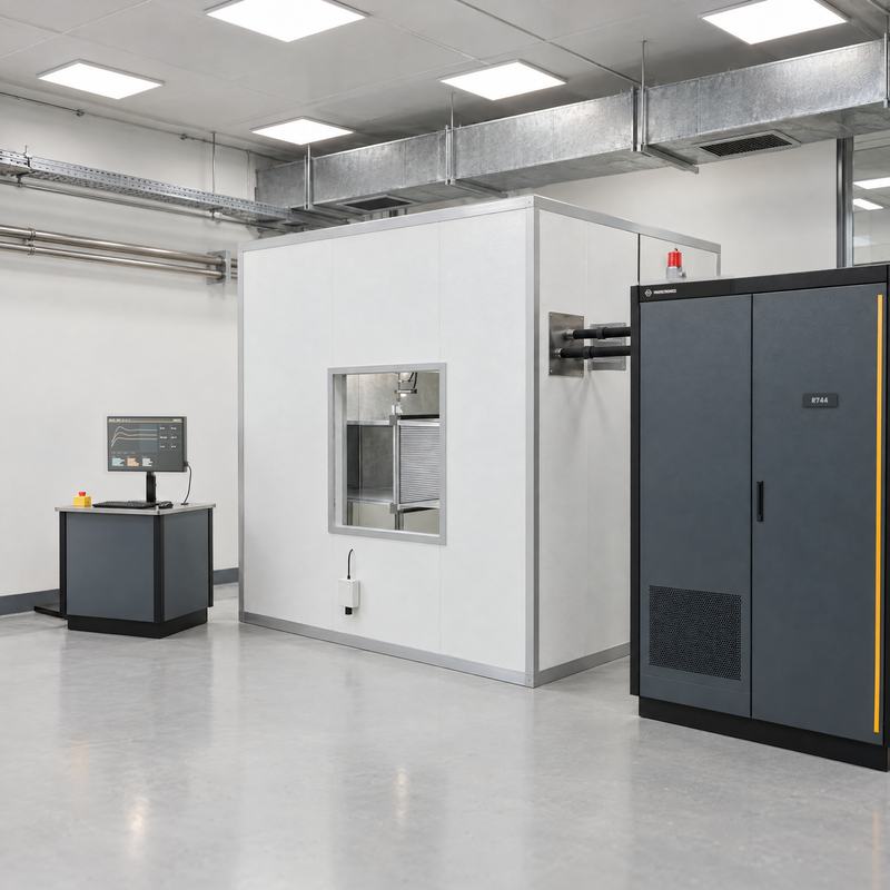
Calorimeters for heat exchangers

Visualisation · Calorimeter with measurement chamber

For heat exchangers, Profectronics builds calorimeters: for condensers, gas coolers, coolers, charge air coolers and oil coolers. The values that follow apply to the calorimeter and not to the conditioning of the heat pump.

  • Air flow rate up to 8 000 m³/h
  • Steady-state control deviation ± 0.1 K
ETHERNET · OPC UA · MODBUS TCPPLCANDCONTROLSOURCE CONDITIONINGCLIMATIC CHAMBER · −25 TO +55 °CFANCOOLERHEATERHUMIDIFIERBRINE CIRCUIT · −15 TO +40 °CPUMPTEMP. CONTROLMFV 111TEST SPECIMEN · HEAT PUMPREFRIGERANTCOMPRESSOREVAPORATORCONDENSER4-WAY VALVEEXPANSIONAIRTI101SINK CONDITIONINGFLOW 35 / 45 / 55 °CREHEATERMFV 301PUMPRECOOLERTI202FI303Flow, conditionedReturnAir flowRefrigerant circuitBusMeasuring point (TI temperature · FI flow)Design values, not a project commitment. The source is a brine circuit or a climatic chamber. In air operation, the uniformapproach flow sets the quality of the performance map. The functional specification defines the operating points.
Fig. 2 · Source conditioning as brine circuit or climatic chamber (left), test specimen with refrigerant circuit (centre), sink conditioning (right). Turquoise: flow line with medium flow.
Standards

Standards and traceability

Profectronics designs the test benches for the standards that follow. The functional specification defines the test points from the standards.

  • EN 14511 Capacity and coefficient of performance
  • EN 14825 Part load, calculation of SCOP and SEER
  • EN 16147 Domestic hot water heat pumps
  • EN 305, 306, 1117, 1118 Heat exchangers, if necessary

The proof includes the measuring chain behind the reference to the standard:

  • Measuring instruments calibrated, with equipment number and calibration status
  • Measuring chain documented
  • Test record with time stamp, traceable after one year
Refrigerants and safety

Refrigerants R290 and R744

Test specimens also operate with propane (R290, safety group A3) or with CO₂ (R744). R290 is flammable. R744 operates in the supercritical range. Profectronics also designs the test benches for refrigerants of the safety groups A1, A2 and A2L.

The warning logic and the fault logic are part of the system. The risk assessment for each refrigerant and installation site sets the necessary safety level (performance level, zones, extraction capacity).

Design

Design range

The table gives the limits of the modular system.

FeatureValue (design)
Test specimensBrine/water, water/water and air/water heat pumps, chillers, domestic hot water heat pumps
Sinkup to 80 °C
SourceBrine −15 to +40 °C, air −25 to +55 °C
CircuitsSource and sink with separate control (brine and water)
RefrigerantsSafety groups A1, A2, A2L and A3, with R290 and R744 (CO₂)
StandardsEN 14511, EN 14825, EN 16147
Unattended operationup to 72 h
ConstructionFrame, control cabinet, as an option container or climatic chamber

The values are design limits and not a commitment for a specific project. The functional specification defines the values for your system before Profectronics orders the hardware.

Other focus areas

Other focus areas and enquiry

For the design, 5 items of data are sufficient: test specimen, medium, ranges for pressure, flow rate and temperature, installation site and date. A customer specification helps, but it is not a condition.