Thermal resistance
Rth
From emulator temperature, coolant inlet temperature and electrical power.
Test platform for liquid-cooling cold plates. A chip emulator replaces the chip and applies up to 5,000 W per test line.
The platform conditions the coolant. A chip emulator applies the heat load. The platform measures thermal resistance, pressure drop and transient behaviour.
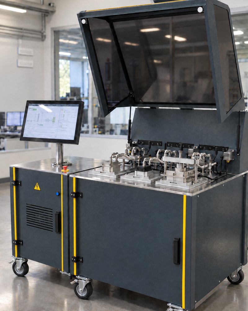
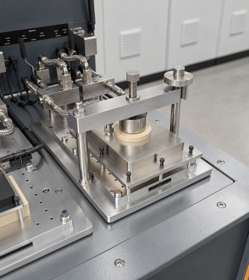
Test frame approx. 1.04 × 1.04 m, electrical unit approx. 0.65 × 0.75 m, both on castors.
Connections: 400 V / 32 A, facility water, compressed air.
A cold plate is qualified at a defined heat flux on a defined area. The emulator replaces the chip.
The platform sets flow rate, temperature and pressure of the coolant and measures the result.
From emulator temperature, coolant inlet temperature and electrical power.
Across the cold plate, over the flow rate, with the selected coolant.
Power profile from a file. Temperatures and flow as a time series.
| Test condition | Value | Note |
|---|---|---|
| Heat load | 5,000 W per test line | 8,000 W option |
| Heat flux | 139 W/cm² on 60 × 60 mm | 500 W/cm² on request |
| Flow rate | 1.5 to 10 L/min | Per test line |
| Coolant inlet | 20 to 45 °C | |
| Coolants | Water, water-glycol, oils, dielectric fluids |
The emulator applies the same heat flux on the same area as the chip.
| Feature | Value | Catalogue range |
|---|---|---|
| Principle | Same heat flux on the same area as the chip | |
| Footprint | 60 × 60 mm | 30 × 30 to 80 × 80 mm |
| Power | 5,000 W | 2,000 to 8,000 W |
| Heat flux | 139 W/cm² at 5 kW | 500 W/cm² on request |
| Heater plate | 8.5 or 6.0 mm thick, Ra < 0.4 µm | |
| Voltage | 12 to 600 V | Matched to the power supply |
The PLC calculates the electrical power from its own current and voltage measurement. The read-back of the power supply is not used for the balance.
Three-phase feed
0 to 400 V / 13 A, 1 rack unit
With temperature limiter
P = U · I, ± 0.5 %
32.0 Ω, 5,000 W
Control: power setpoint profile from file. Release only with flow. Emulator temperature monitored.
The table lists the heater plate sizes with their maximum power.
| Footprint | Max. power | Heat flux |
|---|---|---|
| 30 × 30 mm | 2,000 W | 222 W/cm² |
| 35 × 35 mm | 2,500 W | 204 W/cm² |
| 40 × 40 mm | 3,200 W | 200 W/cm² |
| 50 × 50 mm | 5,000 W | 200 W/cm² |
| 60 × 60 mm | 5,000 W | 139 W/cm² |
| 80 × 80 mm | 8,000 W | 125 W/cm² |
Maximum power: catalogue values of the heater plates. Heat flux: calculated from power and area. The power supply class limits the power. Base configuration: 60 × 60 mm with 5 kW class. 80 × 80 mm with 8,000 W needs the 10 kW class and the 15 kW fluid circuit.
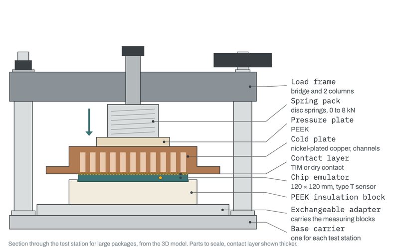
The cold plate sits on the emulator. An exchangeable adapter holds the cold plate and the measuring blocks.
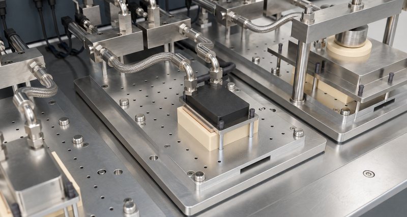
Each cold plate type has its own adapter. Knurled screws hold the adapter. No tools are necessary.
| Adapter example | Mounting |
|---|---|
| Server CPU | Original spring screws with defined torque |
| Accelerator module | Spring screws and guide pins |
| Large package | Up to 120 × 120 mm, load frame, typ. 4 to 6 kN |
| Load frame | Up to 8 kN, adjustable |
| Insulation | PEEK block below the emulator |
Limit: coolant inlet 45 °C, outlet max. 85 °C. A lower inlet temperature extends the range.
| Feature | Value | Note |
|---|---|---|
| Test lines | 1, expandable to 3 | |
| Flow rate | 1.5 to 10 L/min per line | 0.2 to 1.5 L/min option |
| Coolant inlet | 20 to 45 °C | Outlet max. 85 °C |
| Pressure | 1 to 3 bar abs | |
| Pressure drop | 80 to 1,500 mbar | Oils from 35 °C |
| Thermal capacity | 7.5 kW, water | 15 kW option |
| Software | Data logging with export |
One contract for all project phases.
Founder. Quotation, contract, acceptance, quality management, conformity.
Founder. Design, project management, commissioning.
Engineering in Linz, production in Neuhofen an der Krems, Austria.
