
Media brought exactly to the required condition
Temperature, pressure, flow rate and humidity as the boundary condition of a test — designed for test tasks from a single component up to a large-engine test field.
Sizes
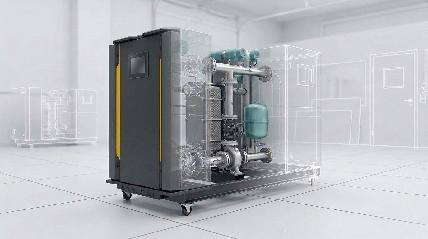
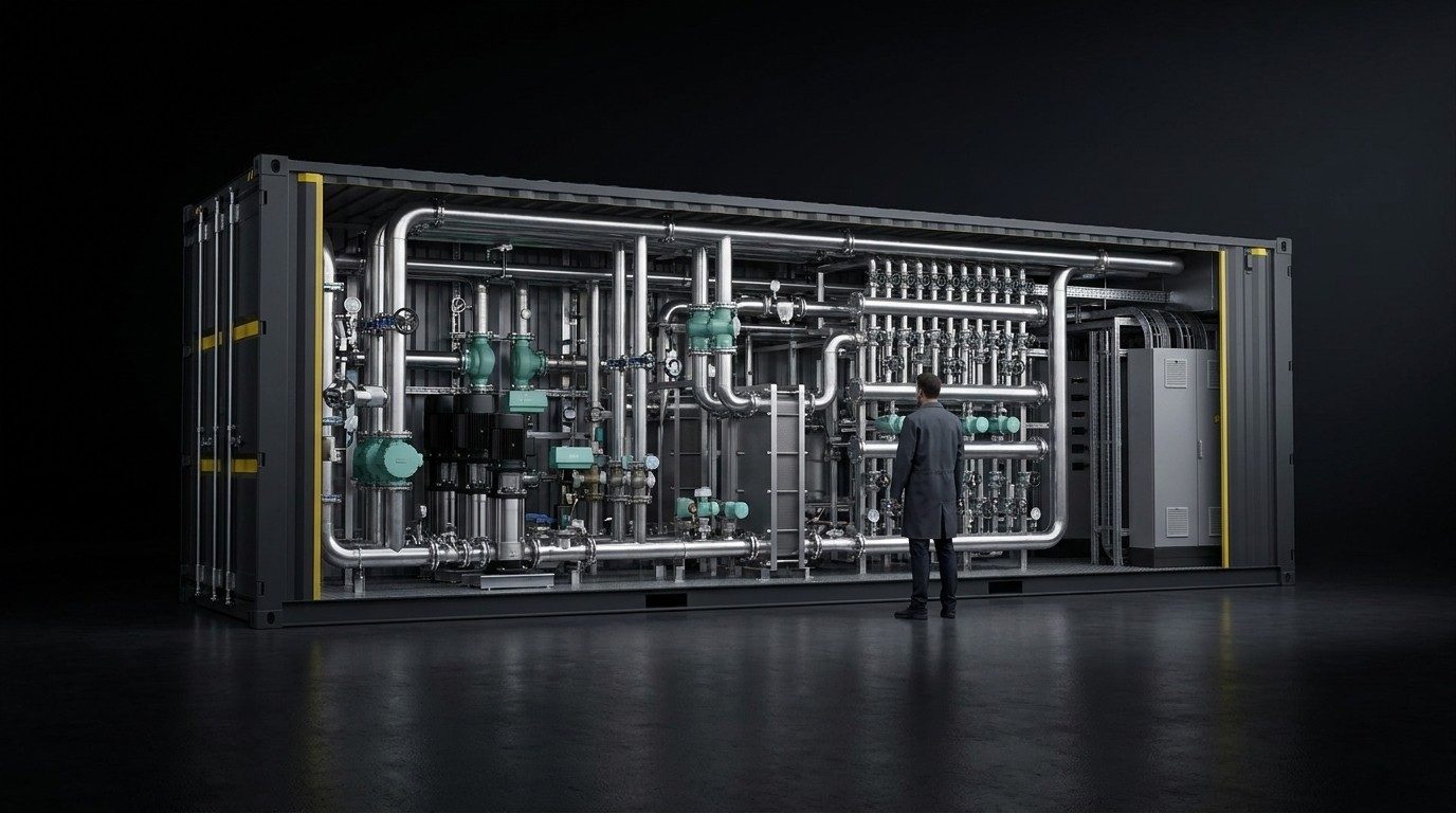
From a trolley to a container
Medium
Water · glycol · oil · dielectric fluids
Fuel · air · gas
liquid, gaseous, two-phase
Conditioning
Temperature · pressure · flow rate
Humidity for gases
up to 2.5 MW per circuit
Control
Feedforward · observer
adaptive and predictive
down to ± 0.1 K at steady state
Test process
Operation · messages · enable
A record for every test run
Development and series production
Engineering Range
Temperature, pressure, flow rate and thermal power are designed for the particular test task.
- Temperature
- −30 … +160 °Cdepending on medium and pressure
- Pressure
- −0.8 … 500 barpressure rating up to 700 bar
- Flow rate
- 3 l/h … 180 m³/hliquid; air up to 8,000 m³/h
- Thermal power
- up to 2.5 MWper circuit
- Control accuracy
- down to ± 0.1 Kat steady state; up to ± 0.5 K during a load step
- Temperature gradient
- 0.1 … 4 K/sdesigned to suit the test task
- Humidity
- 10 … 90 % RHsteam humidifier, adsorption dryer
- Conformity
- CEMachinery, Pressure Equipment, Low Voltage and EMC Directives, ATEX where required
Eight media, each with its own requirement
conductivity monitored
concentration and quality monitored
0.5–600 mPas, vacuum degassing
material compatibility
FKM · FFKM · PTFE, stainless steel
humidity actively controlled
leak tightness, purge concept, enabling chain
design based on substance data
Operating range by application
Thermal power and medium temperature for each application field — the span we design within.
The method follows the controlled system
Dead time from the transit time in the pipework, temperature-dependent plant parameters, states in the test item that cannot be measured — each of these properties calls for its own approach.
State control with feedforward, Kalman-Bucy filter and parameter tracking · section of the plant to ISO 10628, designation to EN 62424 · state estimation as a live display, figures shown as an example
| Method | Property of the controlled system | Effect |
|---|---|---|
| Model-based feedforward | known load setting | The operating point is calculated instead of building up through the control deviation |
| Disturbance feedforward | measurable load change | The disturbance acts on the actuator before it reaches the controlled variable |
| Smith predictor | dead time from pipe transit time | The dead time is taken out of the closed loop |
| Gain scheduling | viscosity against temperature | Controller parameters follow the operating point instead of a compromise |
| Adaptive control | changing media and test item masses | Plant parameters are identified and tracked during operation |
| Predictive control | actuator limits, load cycles | Setpoint tracking under constraints on power and actuator travel |
| Kalman-Bucy filter | noisy measured quantities | State estimation at small temperature differences |
| Sliding mode observer | model uncertainty | Robust estimation of states in the test item that cannot be measured |
- Signal interface
- as specified by the test field
- Plant model
- tracked during operation
- Verification
- in the acceptance record
Operation, verification, record
Operating mode, setpoints, model parameters, messages and the enabling chain on one screen. Every message with an identifier, every test run with a record.
Operator interface · figures shown as an example
- Leak tightness verification
- pressure trace
- Operating modes
- Manual · automatic · cycle
- Traceability
- A record for every test run
- Series operation
- cycle time and initial state
Discuss a project
The medium, the operating range and the test task are enough for a first design.
